Carburising Calculation

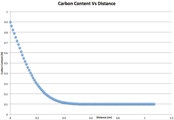
For a 0.1% carbon steel, being carburised at 920 degrees celsius, plot the carbon content as a function of distance below the surface, after 15 hours. The diffusion coefficient is 2.72×10^-7cm^2s^-1 and carbon potential of the gas is 0.9%.

What is the maximum distance below the surface that the carbon has diffused to?

Co = 0.1%

Cs = 0.9%

Dc = 2.72×10^-7cms^-1

t = 54000s

                                     X values (cm)                                                  erf (Y)                                                 Cx (%)
0 0 0.9
0.01 0.046526179 0.862779057
0.02 0.092894291 0.825684568
0.03 0.138947876 0.788841699
0.04 0.184533669 0.752373065
0.05 0.22950312 0.716397504
0.06 0.273713851 0.681028919
0.07 0.317030995 0.646375204
0.08 0.359328423 0.612537262
0.09 0.400489821 0.579608143
0.1 0.440409617 0.547672307
0.11 0.478993728 0.516805017
0.12 0.516160149 0.487071881
0.13 0.551839338 0.45852853
0.14 0.585974443 0.431220446
0.15 0.618521335 0.405182932
0.16 0.64944848 0.380441216
0.17 0.678736644 0.357010684
0.18 0.706378456 0.334897235
0.19 0.732377829 0.314097737
0.2 0.756749272 0.294600582
0.21 0.779517104 0.276386317
0.22 0.800714576 0.259428339
0.23 0.820382954 0.243693637
0.24 0.838570538 0.22914357
0.25 0.855331675 0.21573466
0.26 0.870725764 0.203419388
0.27 0.884816268 0.192146985
0.28 0.897669759 0.181864193
0.29 0.909354999 0.172516001
0.3 0.91994208 0.164046336
0.31 0.929501617 0.156398707
0.32 0.938104013 0.149516789
0.33 0.945818804 0.143344957
0.34 0.952714066 0.137828747
0.35 0.95885592 0.132915264
0.36 0.9643081 0.12855352
0.37 0.969131607 0.124694714
0.38 0.973384433 0.121292453
0.39 0.977121359 0.118302913
0.4 0.980393811 0.115684952
0.41 0.983249783 0.113400173
0.42 0.985733813 0.111412949
0.43 0.987887 0.1096904
0.44 0.989747067 0.108202346
0.45 0.991348458 0.106921233
0.46 0.992722464 0.105822029
0.47 0.993897365 0.104882108
0.48 0.9948986 0.10408112
0.49 0.995748942 0.103400847
0.5 0.996468676 0.102825059
0.51 0.997075794 0.102339365
0.52 0.997586177 0.101931058
0.53 0.998013781 0.101588975
0.54 0.998370814 0.101303349
0.55 0.99866791 0.101065672
0.56 0.998914292 0.100868566
0.57 0.999117922 0.100705662
0.58 0.999285647 0.100571483
0.59 0.999423328 0.100461338
0.6 0.999535962 0.10037123
0.61 0.999627795 0.100297764
0.62 0.999702412 0.100238071
0.63 0.999762835 0.100189732
0.64 0.999811598 0.100150722
0.65 0.999850817 0.100119347
0.66 0.999882253 0.100094198
0.67 0.999907365 0.100074108
0.68 0.999927357 0.100058114
0.69 0.999943219 0.100045425
0.7 0.999955762 0.100035391
0.71 0.999965645 0.100027484
0.72 0.999973407 0.100021274
0.73 0.999979483 0.100016414
0.74 0.999984222 0.100012623
0.75 0.999987905 0.100009676
0.76 0.999990759 0.100007392
0.77 0.999992963 0.10000563
0.78 0.999994659 0.100004273
0.79 0.999995959 0.100003233
0.8 0.999996953 0.100002438
0.81 0.99999771 0.100001832
0.82 0.999998284 0.100001373
0.83 0.999998719 0.100001025
0.84 0.999999046 0.100000763
0.85 0.999999293 0.100000566
0.86 0.999999477 0.100000418
0.87 0.999999615 0.100000308
0.88 0.999999717 0.100000226
0.89 0.999999793 0.100000166
0.9 0.999999849 0.100000121
0.91 0.99999989 0.100000088
0.92 0.99999992 0.100000064
0.93 0.999999942 0.100000046
0.94 0.999999959 0.100000033
0.95 0.99999997 0.100000024
0.96 0.999999979 0.100000017
0.97 0.999999985 0.100000012
0.98 0.999999989 0.100000009
0.99 0.999999992 0.100000006
1 0.999999995 0.100000004
1.01 0.999999996 0.100000003
1.02 0.999999997 0.100000002
1.03 0.999999998 0.100000001
1.04 0.999999999 0.100000001
1.05 0.999999999 0.100000001
1.06 0.999999999 0.1
1.07 1 0.1

graph

Polymeric Coatings

Polymers can be used as a protective coating against corrosion and can be favoured over metals due to initial cost, structural properties and service life. There are a certain polymers that have good enough properties that allow them to resist corrosion and in some cases a polymer is used because a metal would otherwise corrode, an example of this is polytetrafluoroethylene (PTFE).

The corrosion resistance of polymer is linked to its polymeric structure, including degree of crystallinity, bond strength and type of bonding.

Newer thermoplastics are also used due to their great corrosion resistance that include: aromatic polyester liquid crystals, polyketones and polyphenylene sulphide. These polymers even have this great corrosion resistance at elevated temperatures. There are clear advantages that make these thermoplastics a better choice than metal, these advantages include: the ability to be moulded, design versatility and potential for parts consolidation (Davis, 2000:293).

Table 1: Chemical resistance of engineering plastics

Material Resistant to Attacked by
Acetals Organic solvents; aliphatic, aromatic, and chlorinated hydrocarbons. Strong acids, alkalis, and oxidising agents
Epoxies Organic solvents; weak acids and alkalis Some epoxies are attacked by strong alkalis; most, by strong acids
Nylons 6 and 6/6 Hydrocarbons; esters; ketones; alkalis Mineral acids; phenols; cresols
Polycarbonates Weak organic and inorganic acids; oxidizing and reducing agents; aliphatic hydrocarbons Aromatic and chlorinated hydrocarbons; alkalis; amines; esters
PBT and PET Alcohols; oils; petroleum; esters; ketones; aliphatic hydrocarbons; weak acids and bases Low-molecular-weight ketones; strong acids and bases
Polyetherimides Mineral acids; weak bases and hydrocarbons; fluorinated solvents and refrigerants Chlorinated hydrocarbons
Thermoplastics polyamides Most organic solvents; dilute acids ands bases; oils
Polytetrafluoroethylene The most inert plastic; resists practically all solvents. Related polymers perform similarly.

Commercial suppliers of Polymeric coatings

ITW Polymers Coatings – This is a company based in North America that provides polymer-based solutions for commercial and industrial use.

http://www.itwcoatings.com/about.php

Indestructible – This company is based in Birmingham makes different types of paints for various applications such as, engine parts, marine parts, frames and parts for planes.

http://www.indestructible.co.uk/polymers/

Icon – This is a company based in the UK that makes polymer parts and also polymer coatings working in aerospace, transport, energy and industrial areas.

http://www.iconpolymer.com

Bibliography:

Davis, J.R. (2000) Corrosion: Understanding The Basics United States of America, ASM International.

Review of First Post

In my first portfolio task I analyzed a metal hob ring cover and the way in which had corroded and the reasons why. This post is to review if what I had written is correct or incorrect and the reasons why with the added knowledge I have gained throughout this module.

edited

Firstly the rust has been caused from moisture in the air and when the hob ring cover has been washed and not dried properly, this has corroded due to it coming into contact with water. This is still correct because it is very unlikely that the hob ring cover will have corroded in any other ways.

The methods to prevent this type of corrosion have already been suggested in my original post. These consist of:

  • Use a rust resisting alloy
  • Galvanization of the steel
  • Use coatings such as lacquer or varnish

Corrosion Prevention in Stainless Steels

Sedriks states that ‘Stainless steels are iron alloys containing a minimum of approximately 11% chromium’ (1979:1). This amount of chromium is enough so that the steel cannot rust in unpolluted atmosphere. The stainless steel group is very diverse because different stainless steels contain different elements to change the properties of the stainless steels that allow them to be used for many different applications.

Specific elements are added to stainless steels to provide better corrosion resistance, the following elements do this: Nickel, Nitrogen, Molybdenum, Titanium, Phosphorus, Niobium, Silicon, Copper as well as chromium but without this element the stainless steel wouldn’t be stainless. These alloying elements will be used to prevent certain types of corrosion.

Nickel – If this element is added in amounts greater than 8% then the steel becomes austenitic stainless steel and improves its resistance to oxidation and corrosion. Nickel can benefit other properties of the stainless steel such as the increase in toughness and strength.

Chromium – This is a highly reactive element and creates the passive layer on the stainless steel that prevents further diffision onto the surface of the steel. The more chromium that is present the greater the level of protection.

Molybdenum – This element adds increased corrosion resistance to localized pitting attack and crevice corrosion especially in ferritic stainless steels. Molybdenum is also used to resist the effects of chloride and sulphur, the more molybdenum that is present the better the resistance against higher levels of chloride and sulphur. Molybdenum will also increase high temperature strengths and hardness, when its added to the chromium it will also greatly decrease the chance of steels to decay in service or in heat treatment.

Silicon & Copper – These two elements are added to reduce the susceptibility of corrosion to sulphuric acid in austenitic stainless steels that contain molybdenum. The Silicon will also improve the resistance to oxidisation and can also prevent carburizing at elevated temperatures.

Nitrogen – Nitrogen is used to increase the resistance against localized pitting attack and inter-granular corrosion. The use of nitrogen can help to increase the yield strength in stainless steel which has a lower carbon content.

Niobium – Niobium prevents inter-granular corrosion at the heat affected zone which is cause from welding This element will help prevent the formation of chrome carbides which can take the chromium needed in the microstructure for passivation. Niobium can also increase thermal fatigue resistance in ferritic stainless steels.

Titanium – Prevents inter-granular corrosion. The titanium will stabilise the stainless steel and will form titanium carbides instead of chrome carbides.

Dezincification occurs in copper-zinc alloys that contain more than 15% zinc. The removal of zinc leaves a weak layer of copper that is also porous. This form of corrosion usually happens in brasses that are contact for a long time with water which is high in oxygen and carbon dioxide. There are two major types of dezincification that are layer-type and plug-type. Layer-type is were the majority of the component surface is converted to a uniform corrosion depth whereas plug-type produces small pockets at the surface of the material (Davis ,2000:159).

The prevention of dezincification can be achieved by choosing specific alloys:

  • Brasses containing 85% or more copper are more resistant to dezincification.
  • Brasses which contain 1% Tin have good resistance to dezincification.
  • The addition of small amounts of phosphorus, arsenic or antimony to admiralty metal inhibits dezincification.

Bibliography

Sedriks, John A. (1979). Corrosion of Stainless Steels. 1st ed., United States, John Wiley & Sons Inc.

Davis, J.R. (2000) Corrosion: Understanding The Basics United States of America, ASM International

Corrosion Doctors. Stainless Steel Corrosion. [online]. http://www.corrosion-doctors.org/MatSelect/corrstainsteel.htm

Chase Alloys Ltd (2012). Effects of Alloying Elements in Steel. [online]. http://www.chasealloys.co.uk/steel/alloying-elements-in-steel/

The Stainless Steel Information Center. Role of Alloying Elements In Stainless Steel. [online]. http://www.ssina.com/overview/alloyelements_intro.html

Key to Metals (2012). Corrosion of Titanium and Titanium Alloys. [online]. http://www.keytometals.com/Article24.htm

Corrosionpedia (2014). Dezincification. [online]. http://www.corrosionpedia.com/definition/384/dezincification

Corrosion Lab.

Metals can corrode in an aqueous environment which an electrochemical process. There are two main types of corrosion which can occur which are differential aeration and galvanic corrosion. The following experiment has been done to see how different nails corrode in an aqueous environment a show which parts of the nails form the anode and cathode areas of the corrosion. In this experiment the nails that have been used are: iron nails, iron nails which have been half copper coated at the pointed end, iron nail which is half zinc plated at the pointed end and thin zinc and steel strips. The samples were immersed into an agar solution. Two indicators should be added to the agar solution these will indicate the anode and cathode areas on the corroded metal. The indicators which are added are potassium ferri-cyanide which will turn blue in the presence of Fe2+ ions and phenol phthalein which will turn red in the presence of OH ions.

Differential Aeration

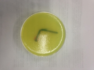
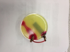
Differential aeration occurs when there is a relative availability of oxygen, this can influence where the anode and cathode form on the metal. The images below show differential aeration which can be seen by the use of indicators, the red color shows the cathode and the blue color shows the anode. The cathode is formed because it’s in contact with the higher concentration of oxygen.

Figure 1 shows differential aeration which can be the seen by the red cathode area and the blue anode area.

The following reactions have occurred:

Anode: Fe → Fe2+ + 2e– 

Cathode: ½ O2 + H2O + 2e → 2(OH)–   

IMG_2195

Figure 1: Corrosion of an iron nail due to differential aeration, it can be seen that at the bend is the anode and the head is the cathode.

Galvanic Corrosion

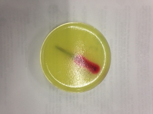
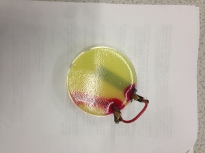
Galvanic corrosion occurs between two dissimilar metals when they are in contact and immersed in an aqueous solution. The more reactive metal will become the anode and the least reactive metal will become the cathode, the use of indicators can show this by turning red and blue.

IMG_2197

Figure 2 shows a nail which is half coated with zinc, the red area shows the cathode area. There is no blue colouration because zinc is more active than iron.

IMG_2194

Figure 3 Shows a half copper plated iron nail connected to a thin strip of zinc. The nail is the cathode and the zinc strip is that anode because it is the more reactive metal.

IMG_2193

Figure 4 Shows an iron nail connected to a thin copper strip. The iron nail is cathode and the zinc strip is the anode because it is the more reactive metal.

Visual Identification of Corrosion Processes

IMG_2204

Figure 5.

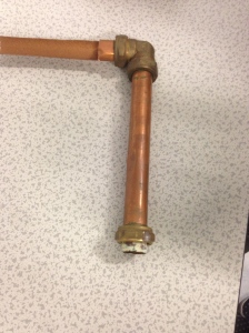
Figure 5 shows a copper pipe which is for water piping in houses. The copper pipe could experience changes in temperatures if is used for central heating because it will frequently have hot water running through it and will also be in contact will water a lot of the time. This environment can easily cause the pipe to corrode by different methods of corrosion. Pitting corrosion often occurs in copper pipes and can be seen at the end of the pipe were it would be connected. The chemistry in the water can influence the formation and propagation of pits. Pitting corrosion can be classified into three groups: hard water, soft water and soft water with a high pH. The holes cause from the pitting corrosion can be fixed by soldering the hole up, replacing the pipes, using an alternate material for the pipes (PVC pipes) and coating the insides of the pipes using epoxy.

IMG_2200

Figure 6.

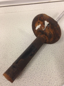
Figure 6 shows the damper from a car, a damper controls the speed at which the suspension reacts to bumps on the road surface. From the picture of the damper it can clearly be seen that it has been corroded so much that it is actually missing bits and has corroded to failure. The corrosion has occurred due to its constant exposure to moisture in the environment; it may also come into contact with gases produced from the car which will also affect the corrosion on the damper. Preventing the rust on the damper can be done by changing the material that is used for this part. Different coating could also be applied to the damper such as rust prevention coatings and corrosion prevention coatings; these will help keep the damper from being attacked by corrosion.

Corrosive Environments

Environment

The corrosion of steel in concrete is very important because the corrosion can affect the stability and durability (Shreir, 1994). Steel will corrode when in the presence of air and water (Broomfield, 1996). Bacteria can also cause corrosion of the steel (Broomfield, 1996).

When the steel is in the concrete it’s in an alkaline environment which will not corrode the steel because steel corrodes in acidic conditions (Broomfield, 1996). Broomfield states that ‘The alkaline condition leads to a ‘passive’ layer forming on the steel surface. A passive layer is a dense, impenetrable film which, if fully established and maintained, prevents further corrosion of the steel.’ (Broomfield, 1996).

Concrete can react with carbon dioxide in the atmosphere that can reduce its pH so that it’s more acidic and then the steel in the concrete will become no longer passive. This process is called carbonation. The carbonation spreads from the concrete to the steel and this can cause the steel to corrode. The concrete can give the steel a significant amount of protection because the rate of carbonation depends upon porosity, permeability, cement content as well as other factors (Shreir, 1994).

‘Chloride-induced rebar corrosion is one of the major forms of environmental attack to reinforced concrete’ (Shi, 2012). The buildup of corrosion products in the pores of the concrete near the steel rebars can build up and cause the steel to crack which allows moisture and chloride ions to corrode the steel (Shi, 2012). The steel will only start to corrode when the concrete surrouning the steel is contaminated with chloride ions which exceed the concentration value (Shi, 2012).

The steel in concrete can be exposed to saltwater because the water can influence permeability and this can then initiate corrosion due to the chloride in the environment. In an environment where this is a lot of chloride present the increase in the water content can have a massive impact for the structural life of the steel (Hover, 2011).

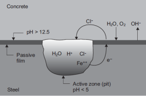
Chloride attack

Figure 1: Chloride attack

Corrosion Mechanisms

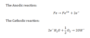
There are two process which can break down the passive film on the steel, these are carbonation and chloride attack (Broomfield, 1996). An anodic reaction occurs when steel in concrete corrodes and two electrons are given off. These two electrons must be consumed elsewhere on the steel surface to retain electrical neutrality. A cathodic reaction occurs to consume these electrons (Broomfield, 1996).

Anodic & Cathodic Reaction

Figure 2: The anodic and cathodic reaction

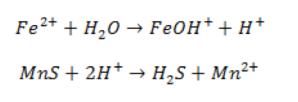
Broomfield states that ‘Ferrous hydroxide becomes ferric hydroxide and then hydrated ferric oxide or rust’ (1996) these are the reactions that occur after the anodic and cathodic reactions.

Ferrous Hydroxide

Figure 3.

Pitting is normally the start of the corrosion of steel in concrete. The presents of chlorides are attracted due to the electrochemical potential difference that makes the passive layer more vulnerable to attack. The corrosion of steel will start, hydrogen sulphide will form from sulphide inclusions and also hydrochloric acid will form from the the chloride ions. A pit will form and rust may cover it (Broomfield, 1996). The following reactions will occur:

iron

Figure 4.

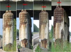
steel rebar corrosion

Figure 5: Corrosion of a steel rebar over four years. (Image taken from Salit Speciality Rebar http://stainlessrebar.com/stainless-rebar-is-cost-effective/a-look-at-corrosion/ )

Bibliography

Broomfield, John. P. (1996). Corrosion of Steel in Concrete: Understanding, Investigation and repair. Spon Press.

Shreir, L.L, Jarman, R.A. and Burstein, G.T. (1994). Corrosion: Volume 1. Butterworth-Heinemann.

Shi, Xianming. Xie, Ning. Fortune, Kieth and Gong, Jing (2012). Durability of steel reinforced concrete in chloride environments: An overview. Construction and Building Materials, 30 (1), 125-138.

Hover, Kenneth C (2011). The influence of water on performance of concrete. Construction and Building Materials, 25 (7), 3003-3013.

Friction Stir Welding

Frictions stir welding is a solid state sintering joining process which is relatively new, energy efficient and environmentally friendly. This welding technique is widely used and hugely appreciated, Mishra states ‘FSW is considered to be the most significant development in metal joining in a decade’ (Mishra, 2005:1).

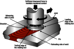
This welding technique works by using a rotating cylindrical tool, which is made of tool steel, with a probe on the end of it. The tool is plunged onto the work piece which is rigidly clamped down and moved along the surface of the work piece which going to be welded. Welding is achieved by friction from the tool which heats up the material. The weld is then categorized into three zones which are:

  • Thermally affected zone – the grain structure is not affected by the welding
  • Thermomechanically affected zone – the grains are severely twisted
  • Dynamically affected zone – old grains disappear and numerous small grains recrystallize

Heating during the welding can cause considerable loss in strength of the material (Kou, 2003:370).

Friction stir welding

Figure 1: Diagram of friction stir welding (Taken from Friction Stir Link http://www.frictionstirlink.com/desc.html )

(Kou, 2003:370).

Materials that are friction stir welded

Friction stir welding is used on aluminium alloys such as 2xxx, 5xxx, 6xxx and 7xxx. Some of these aluminium alloys are nearly unweldable by fusion welding techniques. This technique can also join dissimilar metals to make hybrid components. Other materials that can be friction stir welded are non-ferrous materials (Mg, Cu, and Ti etc.), steel and even thermoplastics (Mishra, 2005:48)

Applications of the materials

In the Aerospace industry there is a high demand for high-strength aluminium alloys which are used for different parts on an aircraft. These high-strength alloys are difficult to weld using conventional fusion welding techniques due to hot cracking during welding. The alternate method is friction stir welding which is a successful technique when used on these high-strength alloys, this method is also more cost effective and less complex than riveting (Mishra, 2005:61).

Friction stir welding is used to weld armour for the military as it proves better than MIG welding because it has better resistance to exfoliation corrosion and stress corrosion cracking. Friction stir welded materials will also have better mechanical properties than gas metal arc welded materials and gas tungsten arc welding. This method of welding is better for equipment used by the military because the materials will last longer (Mishra, 2005:62).

Bibliography

Kou, Sindo. (2003) Welding Metallurgy New Jersey, Wiley-Interscience

Mishra, R.S. (2005). Friction stir welding and processing. Materials Science and Engineering, Vol 50, 1-78

Intergranular Corrosion & Hydrogen Damage

Intergranular corrosion

Davis defines Intergranular corrosion ‘as the selective dissolution of grain boundaries, or closely adjacent regions, without appreciable attack of the grains themselves’ (Davis, 2000:151). The grain boundaries close down due to the potential differences between the grain-boundary region and any precipitates, intermetallic phases, or impurities that forms at the grain boundaries. The mechanism for intergranular corrosion will vary for each alloy system (2000:151). For example, Knife-line attack is the ‘Intergranular corrosion of an alloy, usually stabilized stainless steel, along a line adjoining or in contact with a weld after heating into the sensitization temperature range’ (2000:509). ‘Welding Is the common cause of the sensitization of stainless steels to intergranular corrosion’ (2000:152). Weld decay occurs during welding as a result of sensitization in the heat-affected zone (2000:515).

The materials that can be affected are austenitic stainless steels, aluminium alloys that contain intermetallic compounds, ferritic stainless steels, such as type 430 and 446, and also nickel base alloys which include Inconel alloys 600 and 601, Incoloy 800, Incoloy 800H, nickel 200 and Hastelloy B and C (2000:151-155). Prevention of intergranular corrosion can be different for different alloys.

The prevention of intergranular corrosion is important and varies for the different types of alloys. For austenitic stainless steels the carbon content needs to be controlled or by the addition of elements such as titanium and niobium which have more stable carbides than the ones from chromium. The more stabilized grades of austenitic steel are more resistant to sensitization by long-term exposure at high temperatures that make them a better material choice when service requires them to be exposed to these higher temperatures (2000:154). One or a combination of the following methods can also prevent intergranular corrosion in ferritic stainless steels and nickel-base alloys: ‘Keeping the alloy in the solution heat-treated condition at all times. Limiting interstitial elements, primarily carbon and nitrogen, to the lowest practical levels. Adding carbide-stabilizing elements, such as titanium, niobium along with a stabilizing heat treatment where necessary’ (2000:155).

Hydrogen Damage

Hydrogen damage is a general term that is were the load-carrying capacity of the metal is reduced by hydrogen. The different types of hydrogen damage are:

  • Hydrogen embrittlement
  • Hydrogen-induced blistering
  • Cracking precipitation of internal hydrogen
  • Hydrogen attack
  • Hydride formation

Hydrogen embrittlement occurs when steel that contains hydrogen is stressed in tension because the hydrogen in the steel reduces the tensile ductility. The hydrogen in the steel comes from electrochemical processes involving the discharge of hydrogen ions (Davis, 2000:181)

Hydrogen-Induced blistering happens to lower strength steels that have been exposed to hydrogen-charging conditions. Hydrogen is generated at the surface of the metal and diffuses inwards which can build up enough pressure to produce internal cracks. If these cracks are just below the surface of the metal the hydrogen gas pressure can build up enough in the crack so that the exterior layer can be pushed up which would resemble a blister (Davis, 2000:184).

When a metal is melted it can pick up hydrogen because the melt has a higher solubility for hydrogen than when it is in its solid form. When the melt cools hydrogen diffuses and precipitates in voids and discontinuities that produces features that result from the decreased solubility of hydrogen in the solid metal. This will form cracks from the precipitation of internal hydrogen (Davis, 2000:185).

Hydrogen attack occurs when steel is exposed to high temperature and high-pressure hydrogen. The absorbed hydrogen in steel reacts with carbides to produce methane bubbles that grow at grain boundaries and form fissures. These fissures that are formed are what cause the failure of the steel (Davis, 2000,186).

Hydrogen is picked up in the metal during melting or welding and hydride formation occurs though cooling. The hydrides in the metal can cause an increase in strength but a decrease in toughness. The hydride particles often form platelets with a preferred orientation in the lattice. Applied stresses on the material can cause preferential alignment of hydrides and so the hydride phase has a much lower ductility than the matrix (Davis, 2000:188).

The first two from the list mainly affect steels, cracking precipitation affects various alloys, hydrogen attack affects steels. Hydride formation affects transition, rare-earth alkaline earth metals and alloys, some of the important metals include titanium, tantalum, zirconium, uranium and thorium (Davis, 2000:180-188). Hydrogen embrittlement, Hydrogen-induced blistering and Cracking usually occur at ambient temperatures whereas hydrogen attack happens at higher temperatures (Davis, 2000:180).

Hydrogen damage can be prevented by changing the materials being used, altering the stress level on the material and the environment that the material is in. Changing the material to one with a higher resistance to hydrogen would be beneficial. Coatings and linings can be applied to the surface of the material that will help shield it from the environment. Tempering can be done to the metal to reduce hydrogen. Surface preparation techniques are used to improve resistance to cracking. Lowering the stress on the component so that its below the value for hydrogen embrittlement, this can be done by increasing the cross section of the component, avoiding stress raisers in the design, reducing residual stresses through heat treatment and reducing the load (Davis, 2000:188-189).

Bibliography:

Davis, J.R. (2000) Corrosion: Understanding The Basics United States of America, ASM International

Rosenberg, Samuel J and Darr, John H. (1948) Stabilization of Austenitic Stainless Steel United States of America, National Bureau of Standards

Schutze, Michael. (2000) Corrosion and Environmental Degradation, WILEY-VCH

Degradation of a Household Item

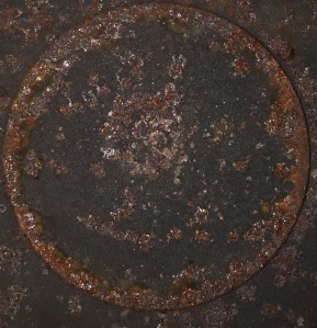
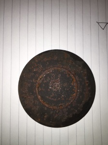
The picture shows a metal hob ring cover which is made of steel. It can clearly be seen from the pictures that the underside of the cover has rusted. The rust has formed due to it coming into contact with air moisture and not being kept dry, the hob that this cover has been taken from is also quite old so the rusting has had a lot of time to develop. Stainless steel could have been used instead of the steel as it will have a longer working life and wouldn’t corrode.

IMG_0119

Prevention of the hob cover could also have been done by various techniques. There are many rust-resisting alloys that could have been used like stainless steel because this forms a passivation layer which will reduce the environmental impact on the hob cover. Galvanization of the steel could also be done and this where the steel is coated with zinc, the zinc will corrode instead of the steel and will therefore protect it. The steel can also be protected by using a coating paint, lacquer or varnish which will isolate the steel from the environment.

edited